
Check our products
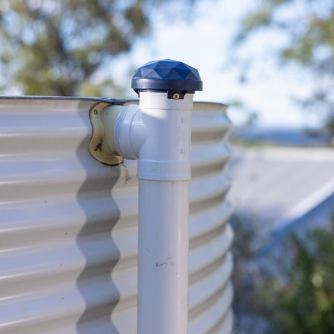

Steel Tank with T-Piece
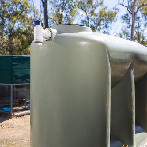

Polyethylene Tank T-Piece
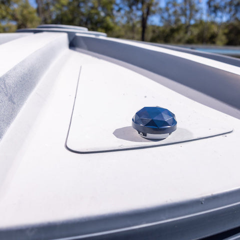

Polyethylene Tank End Cap


Concrete Tank Reducer
Installation of the X42 Tank Starter Kit and additional Sensor Nodes is DIY.
- Installation with a T-Piece for a 90 mm Stormwater Overflow
- Installation with an End Cap
Sensor Node Installation T-Piece
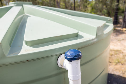

Installation with a T-Piece for a 90 mm Stormwater Overflow
The Node is designed to fit on a standard 90m stormwater pipe.
Items needed for installation, not supplied
- 1 x 90mm 90° Female and Female PVC Stormwater Junction – T-Piece.
- 3 x Screws (Stainless or Hot-dipped galvanised self-tapping).
- An additional short length of 90 mm pipe
- Roof and Gutter Sealant.
Tools
- Drill or screwdriver.
Note
- When installing over a high flow outlet, extend the neck at least 150 mm to let the water pass.
Step by Step
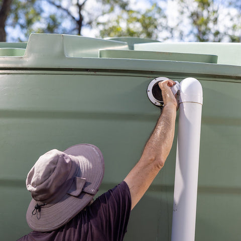

Remove existing Stormwater Pipe
- If present, remove the existing stormwater fittings from the overflow of the tank.
- Remove Elbow piece if connected.
- Check inside the tank the fitting type, elbow or straight, to set fill height later.
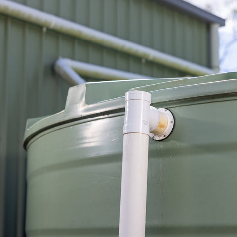

Setting up T-Piece
- Test fit the new 90 mm T-Piece.
- Check if an extension piece is needed.
- If yes, cut the additional required piece to suit.
- Cut the cable tie of the sensor cable without damaging the cable.
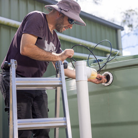

Installation of the sensor
- Insert the sensor from the top and pull it out of the middle of the T-piece.
- Gently insert the sensor into the tank, including the excess cable.
- Apply sealant to joints. Set the T-Piece on top of the stormwater pipe and connect it to the tank.
IMPORTANT: Ensure no sealant is transferred to the metal piece of the sensor.
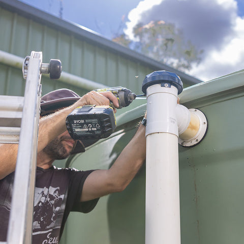

Secure Node
- Set Node on top of the T-Piece.
- Secure Node with three screws to the T-Piece utilising the enclosure tabs.
IMPORTANT: Do not pull the sensor back out until sealant has cured.
NOTE: When installing over a high-flow outlet, extend the neck at least 150 mm to let the water pass. See example on this page.
Sensor Node Installation End Cap
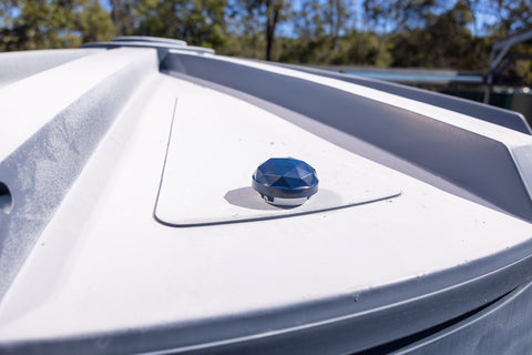

Installation with an End Cap - Polyethylene, Steel and Concrete Tanks
Items needed for installation, not supplied
- 90 mm Push-On PVC Storm Cap – End Cap.
- 5 x Screws (Stainless or Hot-dipped galvanised self-tapping).
Tools
- Drill or screwdriver.
- 25mm min drill bit.
- Plastic Tank: Step-drill or wood drill bit.
- Steel Tank: Step-drill bit.
- Concrete Tank: diamond core drill bit.
Step by Step
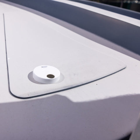

Prepare End Cap and Tank
- Drill a 25-32 mm hole into the End Cap using the supplied template.
- Mark the location on the tank, and drill the same hole size.
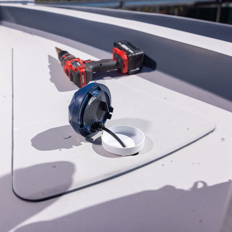

Installing the Sensor
- Remove the cable tie of the sensor cable without damaging the cable.
- Fit the sensor through the hole in the end cap into the tank.
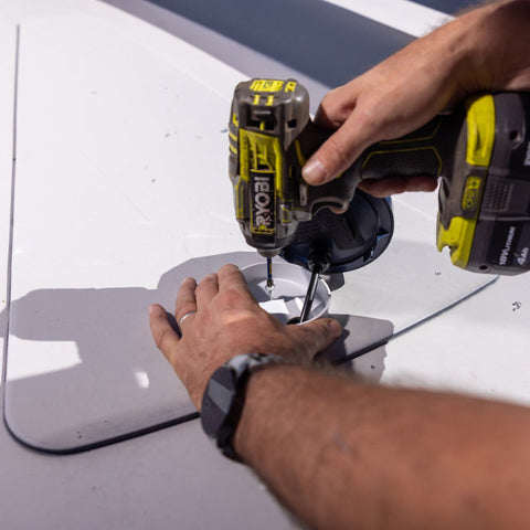

Securing the End Cap
- Secure the End Cap to the tank (screws or adhesive).
- Ensure the 25 mm hole is located at the lowest point to allow fluids to drain back.
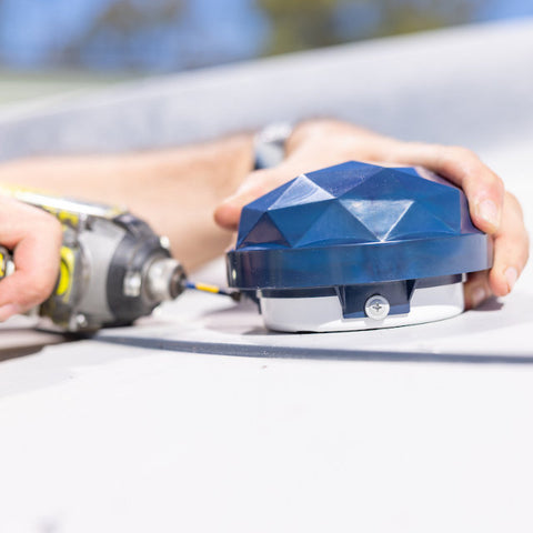

Secure Node
- Set the Node on top of the End Cap.
- Secure the Node with three screws, utilising the enclosure tabs.
Extended Install for Steel Tanks and High Pressure Overflows


To increase the gap between the Sensor Node and the tank
- Use two end caps and a spare length of pipe (minimum 150 mm).
- Drill a 25-32 mm hole into each end cap using the supplied template.
- Mark the location on the tank, and drill the same hole size.


To reduce radiant heat transfer to the Sensor Node
- Secure the 1st end cap on the tank
- Fit the extra pipe
- Fit the 2nd end cap on the top.
- Fit the sensor through the holes in the end cap's into the tank.
- Set Node on top of the extra pipe.
- Secure Node with three screws utilising the enclosure tabs.


For high-pressure overflows, add a 150 mm length of pipe above the T-Piece
- Use spare length of pipe (minimum 150 mm).
- Drill a 25-32 mm hole into end cap using the supplied template.


To reduce possible water ingress into the Sensor Node
- Set the Node on top of the End Cap.
- Secure the Node with three screws, utilising the enclosure tabs.
- Set Node on top of the extra pipe.
- Secure Node with three screws to the T-Piece utilising the enclosure tabs.
IMPORTANT: Do not pull the sensor back out until sealant has cured.
IMPORTANT: Ensure no sealant is transferred to the metal piece of the sensor